

Robotmaster Contouring Module: Offline CAM Programming for Robot Edge Trajectories
The Robotmaster Contouring Module is an offline programming (OLP) and CAD/CAM extension for robots that extracts 3D trajectories directly from boundary edges in formats like STEP and IGES. It is specifically designed for applications such as robotic laser cutting, dispensing, and deburring. The module establishes precise tool center point (TCP) vectors and validates motion within a simulated environment to prevent physical collisions and kinematic errors.
How Does Offline Programming Overcome 3D Edge Tracking Constraints?
Manual pendant teaching is fine for simple planar tasks, but it fails on continuous 3D curves—wasting production time and causing erratic TCP vectors. To maintain strict surface normals, you need exact CAD data, not manual jogging. The Contouring module extracts precise trajectories directly from your 3D models, minimizing downtime and preventing unpredictable wrist singularities on the shop floor.
How Does the Contouring Module Calculate Trajectories?
Extracting 3D Vectors via Edge and Swarf Paths
Instead of manually defining micro-segments along a curve, the module parses the CAD geometry natively. The Edge Path function locks the tool vector to a Bisector, Perpendicular, or Tangential alignment relative to the surface normal. For tapered walls or chamfered geometry, the Swarf setting aligns the tool flute tangentially against straight adjacent surfaces. To streamline continuous tracking, the Chain tangent edges parameter evaluates surface tangencies within a ±25° tolerance, automatically propagating the base path along the workpiece. The Auto Path function allows users to filter out surface features smaller than a defined minimum area in mm².
Preventing TCP Flipping and Kinematic Error
Sharp tangent changes on complex castings often force 6-axis wrists into unpredictable orientation shifts. The Smooth placement algorithm looks forward and backward across a user-defined distance to compute a stable reference direction, bypassing sudden singularities. If a retract transition forces a tool orientation shift approaching 180 degrees, the Angle step between clearances parameter calculates and injects interpolated safe points, maintaining motion strictly within the robot’s mechanical joint limits.
Bypassing Controller Memory Limits with Arc Filtering
High-density point clouds generated during 3D laser cutting can exceed the memory capacity of legacy robot controllers, causing execution stutter. The module compresses the code footprint using the Maximum deviation parameter, balancing point density against geometric accuracy using standard 0.1 to 0.2 mm robotic defaults. An active Arc filter then converts heavy linear point-to-point sequences into 3D arcs based on a 0.1 to 0.4 mm tolerance, optimizing the post-processed file size.
Which Robotic Applications Utilize Contouring Controls?
The flexibility of the Robotmaster Slicer Module unlocks capabilities beyond traditional gantry systems, empowering industries to print larger, more complex, and higher-value parts.
Robotic Trimming & Deburring:
Removing flash from castings requires a stable tool angle to prevent gouging. Engineers lock the orientation to Perpendicular and enable Z Dampen to absorb micro-movements along the Tool Z axis, suppressing chatter marks on the finished edge.
Robotic Dispensing & Sealing
Applying polyurethane gaskets along curved housings requires constant linear speed and a perpendicular nozzle. The software enforces continuous tangent tracking and uses Auto join to cleanly merge disjointed toolpaths sharing identical start/end tool vectors.
Laser Cutting & Arc Welding
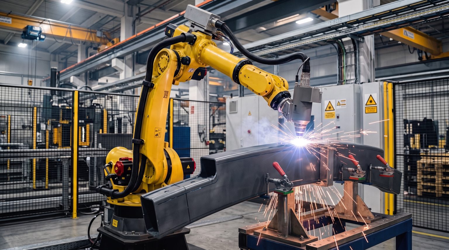
Stamped panels and pipe joints require exact standoff distances and push/pull torch angles. The module projects cut contours directly onto the 3D surface, calculating absolute retract heights (Depth, Feed, Approach/retract, and Clearance) to safely navigate disjointed seams without interference.
Technical FAQ
How does the software handle sharp tangent direction changes?
It utilizes the Smooth placement parameter, which computes a stable reference direction across abrupt corners based on a user-defined smoothing distance, mitigating erratic TCP pivoting.
What is the standard tolerance for balancing path accuracy and code size?
Standard defaults for maximum deviation range between 0.1 and 0.2 mm. Smaller deviations increase trajectory precision, while higher deviations generate compact robot code suitable for older memory-restricted controllers.
How are collisions prevented during disjointed toolpath transitions?
Engineers configure hierarchical retract heights—Depth, Feed, Approach/retract, and Clearance—using absolute or incremental references to ensure the TCP safely clears all part geometry before repositioning.
Discuss Your Offline Programming Bottlenecks
Book a technical walkthrough with our team. We will dive into how the Contouring Module handles your specific robotic applications and demonstrate how parameters such as Smooth placement and Angle step between clearances stabilize 6-axis motion.
 English
 Français
 Deutsch
 Italiano
 Español
 日本語
 简体中文
 繁體中文
 한국어